

[ad_1]

With a dedication to Empowering Farmers with Smart Farming, we build a wheat germination monitoring system. But why this system is needed and how farmers will benefit from this? Let’s understand this first!
Wheat farming is a big deal in many places. To make sure it grows well, you need just the right temperature and moisture.
For wheat seeds to grow, it’s best if it’s not too hot or too cold – about 20°C to 25°C is just right.
But sometimes, things don’t go as planned. If it rains too much right after planting the seeds, they might not grow well, and the young plants can get sick.
As the wheat grows, it faces more challenges like big swings in temperature and not enough rain.
Sometimes, when the weather is cloudy, damp, and chilly, a disease called rust can attack the wheat. And when the wheat is almost ready to be harvested, it likes a steady temperature of about 14-15°C.
Keeping the temperature and moisture levels just right is super important for getting a good crop of wheat.
To assist farmers and wheat producers in dealing with these challenges, we created this project. It’s all about making sure the temperature and humidity are just right for the best wheat crops.
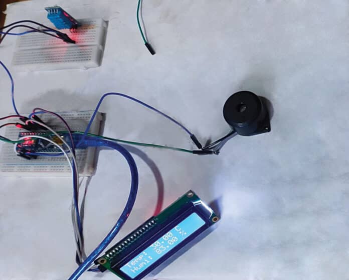
The sample prototype of the wheat germination monitoring system is shown in Fig. 1.
Also Read: Smart Agriculture Irrigation System
Essential components for this project are listed in the below table.
| Bill of Materials | |
| Components | Quantity |
| LCD RG1602A I2C (MOD2) | 1 |
| Arduino NANO (MOD1) | 1 |
| Piezoelectric buzzer (P1) | 1 |
| DHT11 temperature sensor (S1) | 1 |
| 5V power adaptor | 1 |
Wheat Germination Monitoring System – Circuit
The circuit diagram for the monitoring system, aimed at optimizing wheat seed germination, is depicted in Fig. 2.
The circuit’s core revolves around the Arduino Nano (board1), an I2C LCD module (module2), a DHT11 humidity and temperature sensor (S1), jumper wires, a breadboard, a piezo buzzer, and additional essential components.
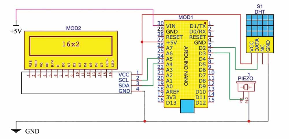
The heart of the project is Arduino Nano. A piezo buzzer has been integrated to sound an alarm when the temperature exceeds 25°C.
The LCD screen is utilized to exhibit the field’s temperature and humidity. The DHT11 sensor gauges the surrounding temperature and humidity, relaying the data to the Arduino, which is then displayed on the connected LCD module.
This system can be further enhanced by incorporating an ESP or other Wi-Fi modules to enable remote temperature monitoring.
A standard I2C LCD display (mod2) consists of an HD44780-based character LCD display coupled with an I2C LCD adaptor. These displays are adept at presenting character-based information.
For instance, a 16×2 character LCD can accommodate 32 ASCII characters across two rows.
At the core of the adaptor lies an 8-bit I/O expander chip, the PCF8574, which converts Arduino’s I2C data into the parallel data necessary for the LCD display.
Wheat Germination Monitoring System – Arduino Code
Programming for this project was accomplished using the Arduino 1.8.19 tool.
The DHT11 sensor’s input is directed to Arduino Nano’s pin D2, allowing the display of temperature and humidity readings both for the surroundings and the field on the LCD module.
An attached piezo buzzer, connected to pin D3, serves as an alarm system to signal excessive temperatures.
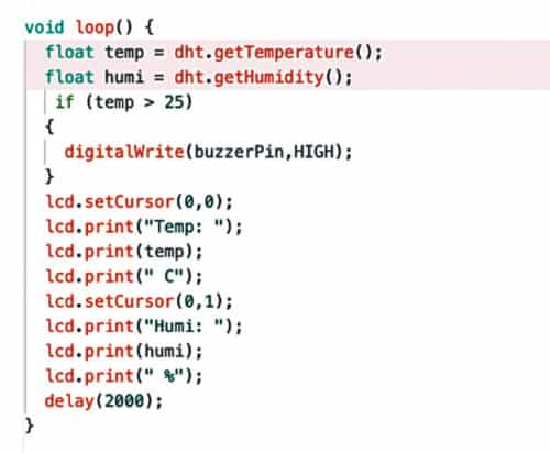
The loop function encompasses the data checking and alarm generation process.
First, write the source code and save the sketch (software) in .ino format.
Before uploading the sketch program to the Arduino Nano board, ensure the correct board is selected. Following board selection, proceed with uploading the source code.
The source code snippet for the loop function is exhibited in Fig. 3.
Testing
Once you’ve uploaded the source code into the Arduino Nano, it’s time to assemble the project. You can do this on a breadboard or a PCB.
After connecting all the parts just like in the circuit diagram, put everything in a suitable case, including the Arduino Nano board.
Now, when you connect the project to a 5-volt power source, you can see the temperature and humidity levels on the screen.
If the temperature gets too high (more than 25°C), a buzzer will make a sound, telling farmers that they need to do something to protect the wheat from bad weather. This helps them take action at the right time.
POC Video Tutorial In English:
POC Video Tutorial In Hindi:
Navpreet Singh Tung is in-charge of the Artificial Intelligence and Robotics Lab at Sandeepani Gurukul in Pathankot, Punjab, India.
[ad_2]
Source link