
[ad_1]

Attention-catching elements prove valuable in warnings, raising awareness of danger, and in exhibitions, providing visual delight. Numerous electronic circuits utilize blinkers, winkers, and LED flashers for these purposes.
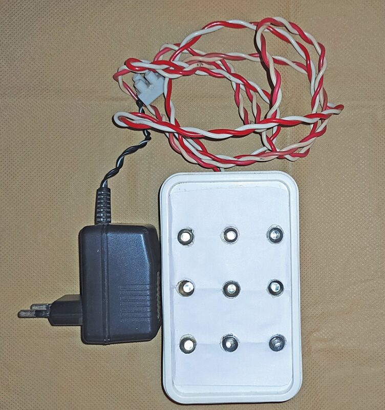
This mosaic display of LEDs, reminiscent of a kaleidoscope, exudes charm and fascination. As this is a straightforward detection system, you have the freedom to construct and present it any way you like for amusement. Electronics Kaleidoscope’s prototype is shown in Fig. 1.

| Parts List | |
| Semiconductors: | |
| IC1 | -555 timer |
| IC2 | -4020 14-bit binary counter/ divider |
| LED1-LED9 | -9 different coloured 5mm LEDs with holders |
| Resistors (all 1/4-watt, ±5% carbon), unless stated otherwise: | |
| R1 | -33-kilo-ohm |
| R2-R10 | -1-kilo-ohm |
| Capacitors: | |
| C1 | -10µF, 25V electrolytic |
| C2 | -0.1µF polyester |
| Miscellaneous: | |
| -Thin enamelled copper wire | |
| -8-pin IC socket (optional) | |
| -16-pin IC socket (optional) | |
| -Small flat plastic box | |
| -Flexible wire | |
| -9V DC adaptor | |
Electronics Kaleidoscope Circuit
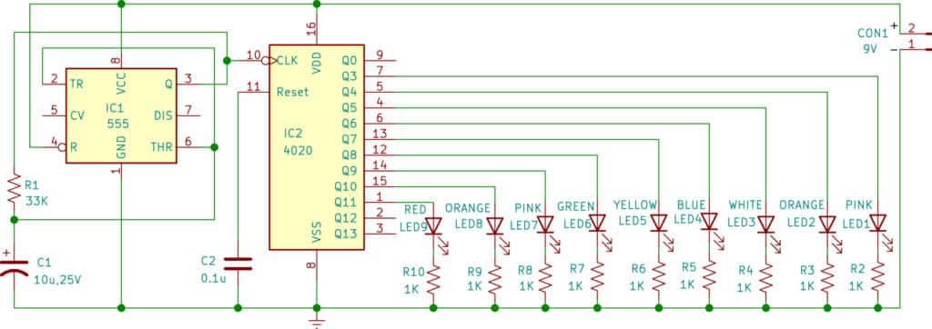
Fig. 2 shows a circuit diagram of an electronics kaleidoscope. The circuit comprises a 555 timer (IC1), a 14-bit binary counter/divider 4020 (IC2), and nine different-colored 5mm LEDs (red, orange, pink, green, yellow, blue, white, etc) with LED holders (LED1 through LED9) and various other components. A 9V power adaptor may be used for the power supply.
Working
The 555 timer is configured as an astable multivibrator. It connects output pin 3 directly to timing capacitor C1 via resistor R1. When the output at pin 3 is high, capacitor C1 charges through resistor R1. When the voltage across the capacitor reaches 2/3Vcc, pin 6 triggers the output at pin 3 to shift to a low state.
The capacitor then discharges back through the same resistor until pin 2 reaches 1/3Vcc, causing the output to change state once again. The capacitor continuously charges and discharges between 2/3Vcc and 1/3Vcc, creating a high and low state at the output pin 3. Here, Vcc is 9V.
As the capacitor charges and discharges through the same resistor, the duty cycle of this basic arrangement is very close to 50%. The series of square wave output pulses produced have a time period (T) equal to approximately 2(0.693)xRxC. The output waveform frequency (ƒ) is, therefore, equal to 0.722/RxC, where R is in ohms and C is in microfarads. The output of IC1 is further fed to the clock pin of binary counter IC2.
The 4020 IC is a 14-stage binary counter, and we have utilized 9 outputs. Each output drives an LED in series with a resistor, producing different patterns before the sequence repeats. In the 4020 IC, the reset pin is connected to the ground with a 0.1µF capacitor. If not connected, the IC will reset repeatedly, resulting in no output on the output pins.
Construction and Testing
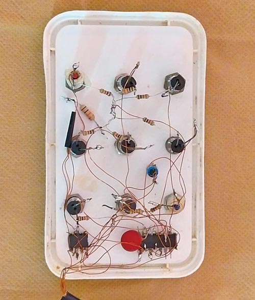
Before assembling the circuit, it would be beneficial to refer to Fig. 2 and Fig. 3 for the schematic circuit diagram and photographs, providing an exact idea about the construction of the device. Assemble the circuit directly in a suitable plastic box after connecting the LED holder to the box. Mount the LEDs on the lid of the box using LED holders.
In a non-conventional approach, we may directly solder thin enameled copper wires to various pins of the ICs without using a PCB or a veroboard. Subsequently, we may glue the ICs on the back side of the lid of the small plastic box and solder the other ends of the enameled copper wires to the other components following the schematic. Each LED is connected through a current-limiting resistor (R2 through R10).
EFY note. Excessive heat from the soldering gun can damage the ICs, so exercise caution and work swiftly! If unsure, consider using IC holders.
Rajeev Nilkanth Deshpande has an M.Sc. in chemistry and has been pursuing electronics as a hobby for over 47 years.
Source link