
[ad_1]

Previously, we explored the ADAS (advanced driver assistance system), which used lidar, camera, and ROS for creation of the map.
Now we are adding an important safety system for ADAS so that you can check the relative speed of moving vehicles.
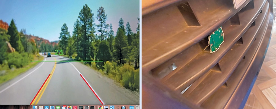
Also, it detects the lane and marks the safe distance from the front vehicle in real time using the radar (see Fig. 1).

There are many lidar and radar systems available in the market for ADAS that can not only detect and map the environment but also tell us the speed of oncoming nearby vehicles as well as padestrians, and accurately measure the distance for ADAS and autonomous driving systems.
But since most of them are laser-based, they might not be very accurate in foggy or very low light conditions.
So here we use the doppler radar that can work in all types of light conditions and foggy environment as well. It is also capable of measuring very high speeds that most of the other systems fail to do.
The components required to build this RADAR ADAS System are listed in the below table.
| Bill of Materials | ||
| Component | Quantity | Description |
| Raspberry Pi/Nvidia Jetson (MOD1) | 1 | SBC |
| Raspberry Pi camera | 1 | CSI camera |
| HB100 radar (S1) | 1 | 10.525GHz radar sensor |
| LM358 amplifier (MOD2) | 1 | Signal amplifier module |
| 5V DC-DC power adaptor | 1 | 5V, 2A DC-DC power converter |
| Wires | 10 | Thin insulated wires |
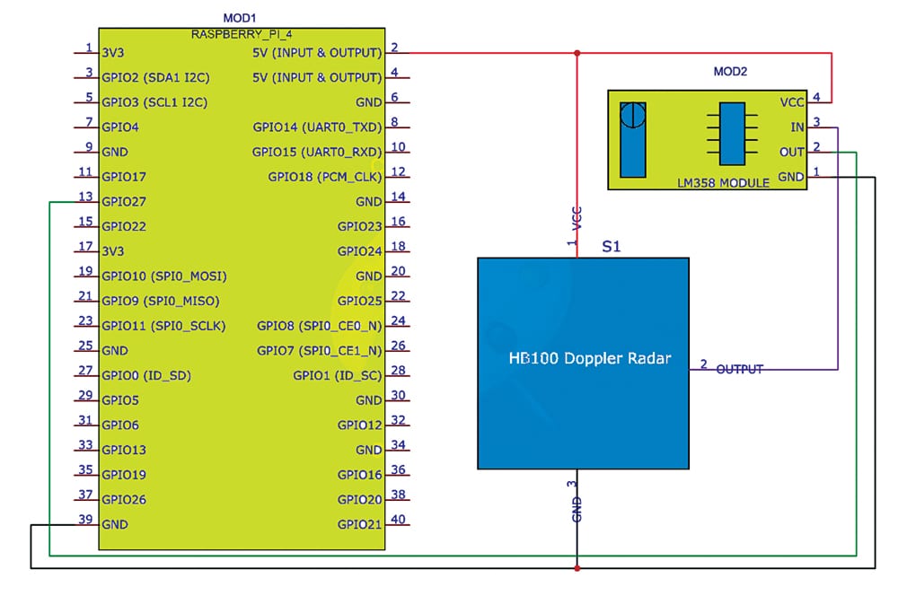
Circuit Diagram
Fig. 2 shows the circuit diagram of the doppler radar in ADAS. It is built around Raspberry Pi (MOD1), LM358 module, HB100 doppler radar, Raspberry Pi camera, and a few other components.
Let us first see how the doppler radar works, how it differs from the other radars, and how we implement it here.
Speed Calculation using Doppler Radar
Doppler radar is based on the principle of doppler effect. Also known as the doppler shift, it describes the change in frequency or wavelength of a wave (such as sound or light) in relation to an observer moving the source of the wave.
The doppler effect occurs because when an object emitting waves (of sound or light) is in motion relative to an observer, the waves emitted by the object get compressed in front of the object and are stretched behind it.
This results in a change in the observed frequency or wavelength of the waves perceived by the observer.
There are two main types of doppler effects for sound:
1. Moving Source and Stationary Observer
If the source of the sound is moving toward the observer, the sound waves are compressed, and the observed frequency is higher (producing a higher-pitched sound). If the source is moving away from the observer, the sound waves are stretched, and the observed frequency is lower (producing a lower-pitched sound).
2. Stationary Source and Moving Observer
If the observer is moving toward the stationary sound source, the same effect occurs, and the observed frequency is higher. If the observer is moving away from the stationary source, the observed frequency is lower.
These radar systems work on the same fundamental principles as other doppler radar applications but are adapted for use in vehicles.
Here is how the doppler radar works in a vehicle:
Transmitting radar signals:
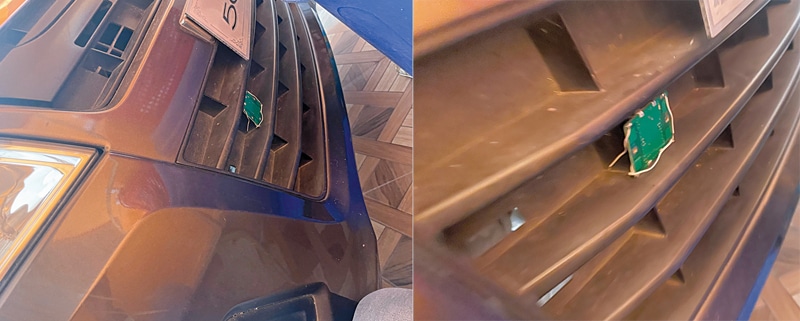
The vehicle’s radar system emits radio frequency (RF) signals in a specific direction, typically in the microwave frequency range. These signals are transmitted using radar antennas or sensors located on the vehicle’s front grille or bumpers.
Reflection and doppler shift:
When the radar signals encounter objects in the vehicle’s path, such as other vehicles, pedestrians, or obstacles, some of the RF energy is reflected back towards the radar antenna.
If these objects are stationary or moving at a constant velocity relative to the vehicle, there is no significant change in the frequency of the returning radar signal.
Doppler shift measurement:
If an object is moving towards or away from the vehicle, it induces a doppler shift in the reflected radar signal. If an object is approaching, the radar signal experiences a positive doppler shift (an increase in frequency). If an object is moving away, it results in a negative doppler shift (a decrease in frequency).
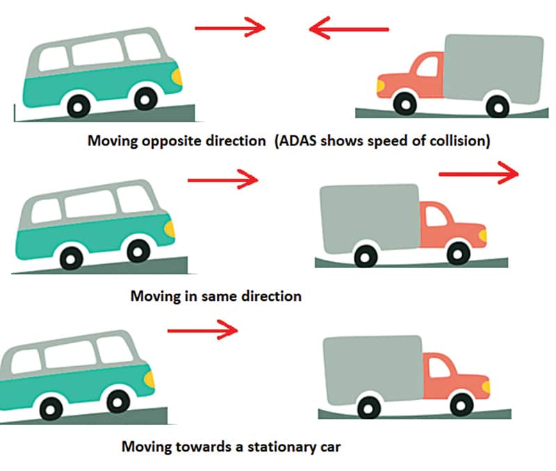
So, here in the doppler radar, we use this principle to measure the speed, which varies in the ADAS as per three different scenarios (see Fig. 3).
Case 1: If the vehicle with radar is stationary and not moving, and any pedestrian or car comes towards or goes away from that car, then the speed it shows is the speed of the car or of the pedestrian coming or going away from the car with radar.
Case 2: If the car with radar is moving, and there is a non-moving car, people, or a wall in front of it, then it shows the speed at which the car is moving towards/away from that stationary car/person/wall.
Case 3: If the car is moving towards another car, then it shows the speed at which they are going to collide with each other.
If both cars are moving in the same direction, then it shows the difference in their speeds. If both are moving in the same direction with the same speed, then the resulting speed it shows is 0, meaning both are not going to collide.
If one of them is moving away faster, then it shows the speed at which the car is going away from the other car. Fig. 4 shows all three scenarios.
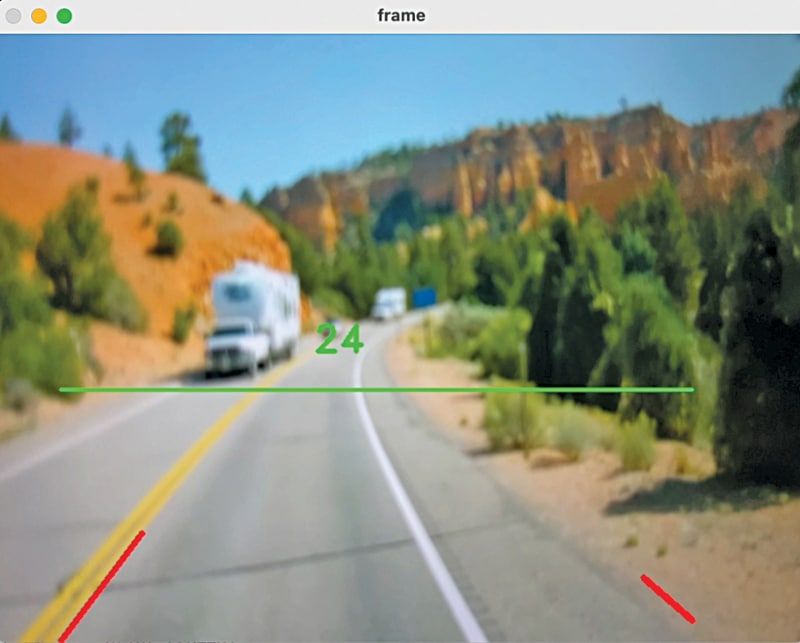
If the car in front of it presses the brake or slows down while the blue car behind it keeps moving or increases the speed, then the ADAS display (Fig. 5) shows the resultant speed at which the car in the rear might collide, and the driver needs to maintain the distance marked in the green line in the display of the ADAS to avoid an accident.
Alternately, if the driver matches the speed of the car in the front, the relative speed is displayed as 0, meaning both are moving at the same speed with respect to each other, and they will not collide.
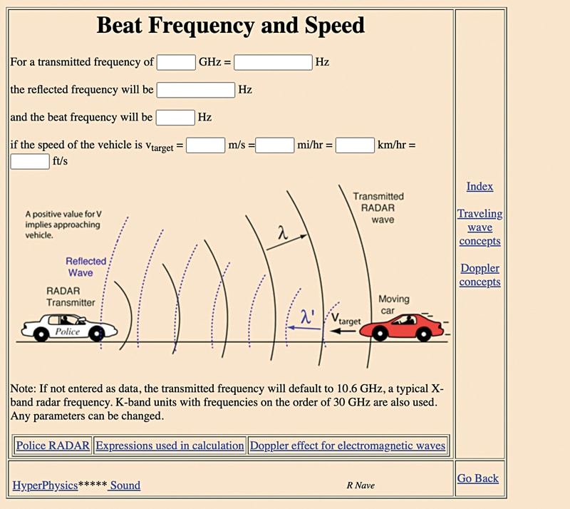
You can check the link http://hyperphysics.phy-astr.gsu.edu/hbase/Sound/radar.html to see how the doppler shift works between the moving targets. The speed is calculated based on the doppler shift and the relation between the frequency of waves. Fig. 6 shows the speed calculator formula for doppler radar using the frequency.
Code for Radar based ADAS
Since we have already delved into coding in the previous ADAS part, it is assumed you already have the Raspberry Pi/Nvidia Jetson ready with an OS and Python IDLE.
We had also created the code for ADAS path and the lane detection, so we carry forward the same code. Add the radar function in this very code and modify it for safe distance marking in real time. You can refer recent EFY issues to check the process once again.
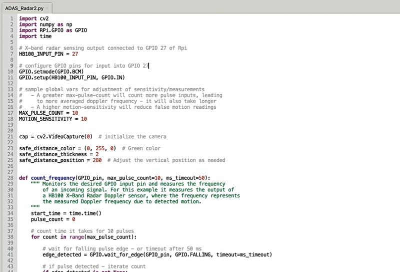
In the code, first, we import the RPI.GPIO Python module to use the GPIO and read the radar data.
Then we set the pulse count and sensitivity value for the radar sensor. Next, we set the pin number on which we connect the radar. Here you can use any free GPIO on the Raspberry Pi; we have used GPIO 27.
Next, create the function to count the frequency, and then implement the formula we got earlier to convert the frequency change into speed.
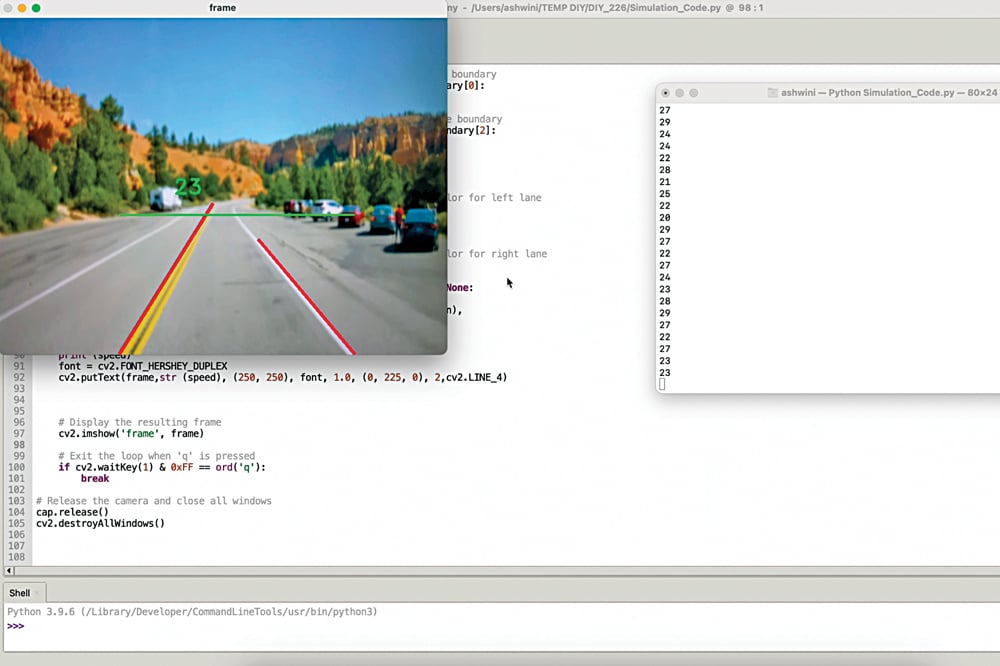
After that, we have created the loop function using ‘while’ where we locate the road and detect the lane lines and also draw a safe distance marking line in real time video frame.
Thereafter, we display the speed detected from the doppler radar. Fig. 7 shows a code snippet of the ADAS and radar.
Construction and Testing
Based on Fig. 2, connect the HB100 radar with LM358 and its output to the Raspberry Pi/Nvidia Jetson GPIO pin as per the circuit diagram.
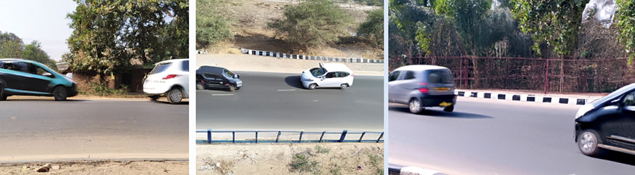
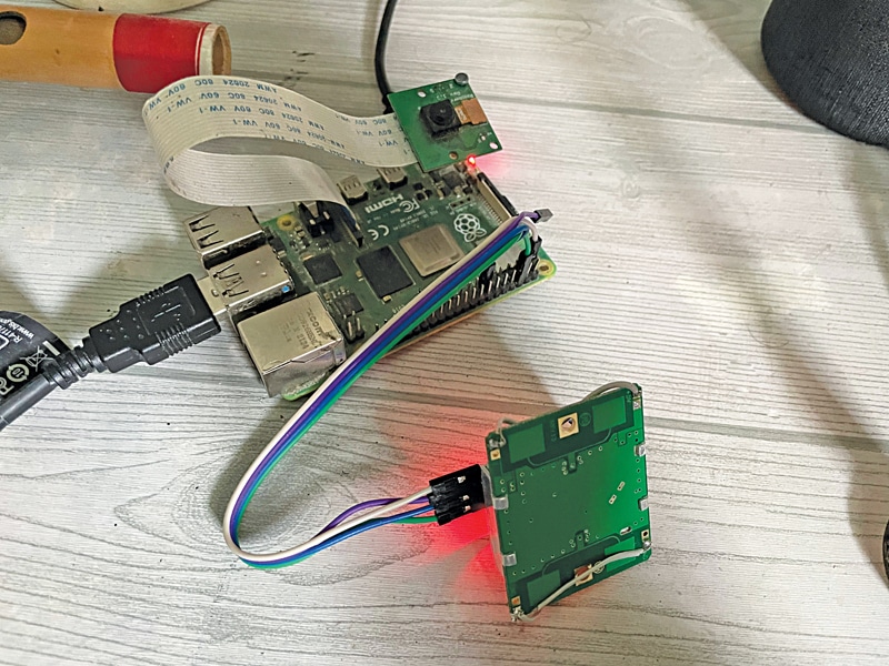
Connect the camera to the camera CSI port of the Raspberry Pi. Then attach the radar and camera in front of the vehicle (see Fig. 9).
After completing the connections, as shown in Fig. 8, power the device with a 5V, 2A DC adaptor and run the code you have created. It will display the speed according to the cases explained earlier and also show the safe distance.
Ashwini Kumar Sinha, an IoT and AI enthusiast, is a tech journalist at EFY
[ad_2]
Source link