

[ad_1]

In this article, we will explore a straightforward method to create an IR remote-controlled FM radio with RDS (radio data system) using the ESP-01 module. We will utilise the Arduino IDE for software development and implementation.
Previously we designed the simple stereo Fm receiver circuit and FM Receiver Circuit.
This time, our primary goal is to design an affordable, compact, lightweight, and portable battery-operated Remote Controlled Stereo FM Radio with RDS message display, complete with IR remote control for user-friendly operation.
Note: We attached the demo video of this Stereo FM Radio project at the end of the article.
While there are several Arduino-based FM radios utilising modules like TEA5767, RDA5807M, and Si4703, they often come with drawbacks such as bulkiness, high power consumption, and excessive cost.
For instance, implementing an FM radio with an Arduino Uno requires a significant amount of power and is not cost-effective. Even the Arduino Nano, though smaller, is relatively expensive and requires a larger number of pins for soldering.
To tackle these limitations, we have chosen the ESP-01 module, which boasts four I/O pins, making it an ideal candidate for our radio. The ESP-01 is easy to program and assemble, requiring minimal expertise.
Unlike microcontroller-based designs, which demand additional components and pricey programmers, the ESP-01’s programming can be accomplished using an inexpensive USB-to-TTL converter.
Furthermore, there are numerous well-established Arduino libraries available for FM radio, IR remote control, and LCD/OLED displays, making software development a breeze.
For I2C communication with the FM radio module, we need two I/O pins. For IR remote control we need one I/O pin. With just three I/O pins we can implement an FM radio with IR remote control along with RDS display using a I2C display (LCD or OLED).
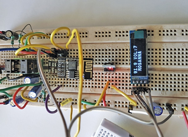
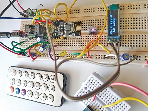
Banking on these advantages, we can quickly develop and integrate an FM radio with shortest development time using ESP-01. Fig. 1 shows the author’s prototype of Remote Controlled Stereo FM Radio with RDS using ESP-01.
To get started, let us look at the components required to build remote-controlled stereo FM radio-
| Table 1: Bill of Materials | |||
| S.No. | Description | Reference | Quantity |
| 1 | 220µF/16V electrolytic capacitor | C7, C8, C9 | 3 |
| 2 | 470µF/16V electrolytic capacitor | C6, C10 | 2 |
| 3 | 100nF capacitor | C1, C2, C4 | 3 |
| 4 | 22nF capacitor | C3 | 1 |
| 5 | LD1117V33 (TO-220) or AMS1117-3.3 (SOT-223) 3.3 volts fixed voltage regulator | IC1 | 1 |
| 6 | ESP-01 or ESP-01S | U1 | 1 |
| 7 | RDA5807M FM stereo module RRD-102 V2 | U2 | 1 |
| 8 | 4 pin 2.54mm header | LCD/OLED | 1 |
| 9 | 3.5mm stereo audio connector | X2 | 1 |
| 10 | 3.7V/500mAh lithium-ion battery | 1 | |
| 11 | TP4056 charger board | X1 | 1 |
| 12 | Micro USB cable | 1 | |
| 13 | Earphone or headphone, 32 ohms | 1 | |
| 14 | SWG#22 wire 75cm length for antenna | 1 | |
| 15 | 23mm 128×32 OLED display SSD1306 | 1 | |
| 16 | 38kHz IR 3.3V remote receiver and IR remote transmitter | U3 | 1 |
Remote Controlled Stereo FM Radio – Circuit
The circuit diagram for the remote-controlled stereo FM radio with RDS using the ESP-01 is depicted in Fig. 2.
It comprises the 3.3V voltage regulator LD117AV33 (IC1), ESP-01 (U1), RDA5807M FM stereo module RRD-102 V2 (U2), 38kHz IR remote receiver 3.3V module (U3), 23mm (0.91-inch) 128×32 OLED display SSD1306, 32-ohm earphones or headphones, and a few other components.

Both the ESP-01 and the IR receiver require a 3.3V supply. You can use a 1117 regulator with a fixed 3.3V output in a TO-220 package or opt for a 3.3V breakout board utilising the AMS1117-3.3 in an SOT-223 package.
To ensure smooth operation, bulk and bypass capacitors are added to both the input and output of the 3.3V regulator. The circuit was tested with both TO-220 and SOT-223 package 3.3V voltage regulators.
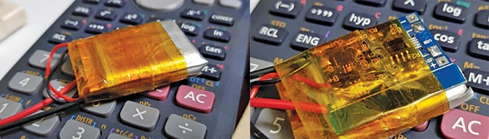
For home installations, a 5V power supply from a 230V AC to 5V DC converter can be employed. Alternatively, you can replace the USB connector (X1) with a 3.7V lithium-ion cell for a lighter, portable setup, as indicated in Fig. 3. The TP4056 charger board is utilised to charge the battery.
Remote Controlled Stereo FM Radio – Code
Compile the code using Arduino 1.8.19 IDE. To begin, install the IDE and ESP boards. You will also need libraries such as Radio-2.0.0, Irremote-3.9.0, SSD1306Ascii-1.3.5, RDSParser, and RDA5807M.
These libraries can be installed via the Arduino library manager found in the ‘Sketch’ menu bar.
The SSD1306Ascii-1.3.5 library is used for the OLED display, indicating the FM channel frequency, radio volume level, and RDS message information.
The RDS message display utilises the Radio-2.0.0 library, while the NEC receiver uses IRremote-3.9.0 for decoding the received IR signal from the NEC remote transmitter.
IR Remote Transmitter and Receiver
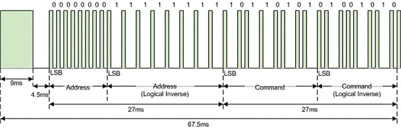
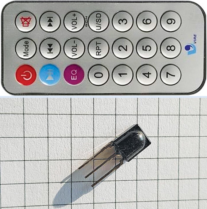
In this setup, we use the NEC protocol IR remote control. Fig. 4 illustrates the NEC message frame, while Table 2 provides a list of NEC remote codes. Fig. 5 displays the IR remote and IR receiver module.
| Table 2: NEC Remote Control Codes | ||
| S.No. | KEY | HEX |
| 1 | ON/OFF | 1FE48B7 |
| 2 | MODE | 1FE58A7 |
| 3 | MUTE | 1FE7887 |
| 4 | PAUSE/PLAY | 1FE807F |
| 5 | PREVIOUS | 1FE40BF |
| 6 | NEXT | 1FEC03F |
| 7 | EQ | 1FE20DF |
| 8 | VOL- | 1FEA05F |
| 9 | VOL+ | 1FE609F |
| 10 | 0 | 1FEE01F |
| 11 | RPT | 1FE10EF |
| 12 | U/SD | 1FE906F |
| 13 | 1 | 1FE50AF |
| 14 | 2 | 1FED827 |
| 15 | 3 | 1FEF807 |
| 16 | 4 | 1FE30CF |
| 17 | 5 | 1FEB04F |
| 18 | 6 | 1FE708F |
| 19 | 7 | 1FE00FF |
| 20 | 8 | 1FEF00F |
| 21 | 9 | 1FE9867 |
The choice of using the NEC protocol is based on the availability, small form factor, and low cost of the IR transmitter. The transmitter operates at a 38kHz carrier frequency.
There are two types of IR receivers: one works within a wide input range (2.8V to 5V), while the other functions solely at 5V.
For this remote-controlled stereo FM radio, we utilise the wide voltage input type of remote receiver, which functions well at 3.3V.
It has only three pins, which can be connected as per the circuit diagram shown here. Ensure that the centre frequency of your IR receiver module is 38kHz.
Tuning the FM radio module can be achieved in two ways: direct frequency tuning or seeking available channels in both directions.
We have opted for fixed frequency tuning in this radio.
The NEC message frames with timing requirements are depicted in Fig. 4. We do not utilise the ‘REPEAT’ feature by pressing a button for a longer duration.
It is important to define the default volume in the code. You will also need to edit the local FM channel frequencies in the source code.
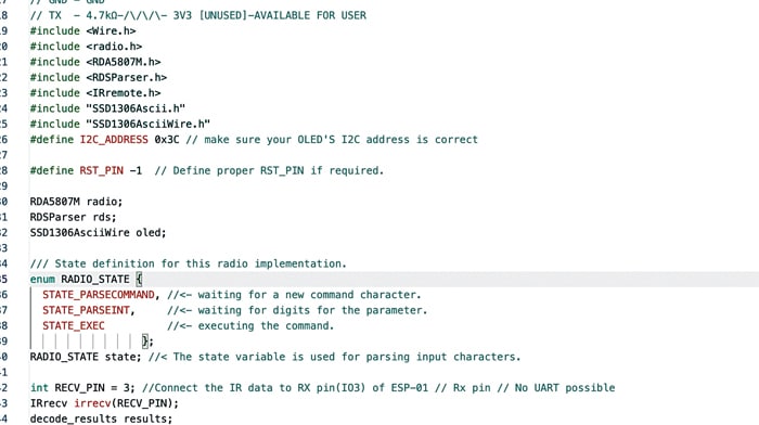
Fig. 6 presents a code snippet, including the necessary library, while Fig. 7 shows a code snippet for setting defaults.
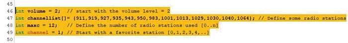
The variable ‘Maxc’ should be set to the total number of stations listed, counting from zero. The ‘Channel=1;’ line defines the default station during startup.
After compilation, flash the ESP-01 using any USB-to-TTL converter or a dedicated ESP-01 programmer board with Tx and Rx lines set at a baud rate of 115200. Fig. 8 showcases the ESP-01 programmer used for flashing.


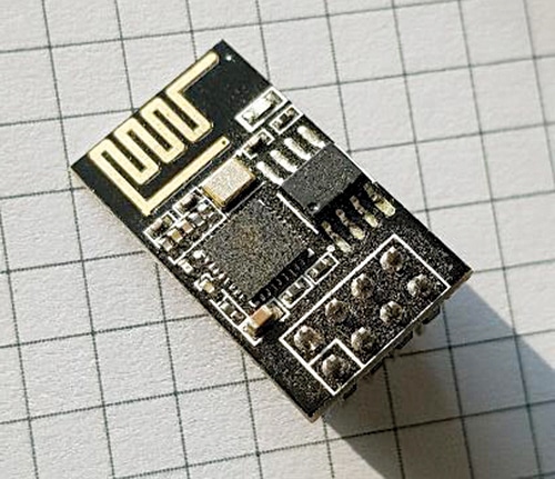
You also have the option to set and change the OLED display variants in the setup function within the code. Two varieties are available, as shown in Fig. 9. Fig. 10 shows the ESP 01 board.
Construction and Testing
After uploading the source code, connect the setup either on a breadboard or a PCB. The connections for the ESP-01 (U1) with other components such as the OLED, IR module, etc. (refer to Fig. 2) are as follows:
1. Connect IO0 to SDA, which is used to control the I2C bus data line. For added safety and reliability, consider adding a 10k-ohm pull-up resistor to 3.3V.
2. Connect IO2 to SCL, which is used to control the I2C bus clock line. Similar to IO0, you can add a 10k-ohm pull-up resistor to 3.3V for enhanced performance.
3. Connect RX to IR Rx I/P, which is used to receive the IR remote control receiver signal. You can directly connect the IR receiver without any additional components, but ensure it operates at 3.3V.
4. Connect RST to RESET. Pull up the RST pin of the ESP-01 using a 10k-ohm resistor with 3.3V.
5. Connect EN to ENABLE. This pin should be connected to 3.3V via a 12k-ohm resistor.
6. Connect 3.3V to 3.3V and GND to GND on both modules.
The FM module used in this radio is the widely available RDA5807M FM stereo module RRD-102 V2, shown in Fig. 11.
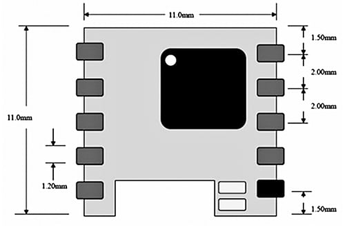
Fig. 12 displays the footprint of the FM IC RDA5807M. This module measures 11x11mm and offers 10 user-accessible pins with a 2mm lead pitch.
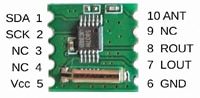
The connection to the FM IC RDA5807M is straightforward, requiring only seven connections.
Pin 1 connects to the SDA pin of the OLED and is also connected to the IO0 pin of the ESP-01.
Pin 2 connects to the SCL pin of the OLED and is also linked to the IO2 pin of the ESP-01.
Pin 5 connects to 3.3V, and pin 6 is grounded.
Pin 7 is used for the left channel and connects to a 3.5mm audio jack via a 220µF capacitor.
Similarly, pin 8 is used for the right channel and connects to a 3.5mm audio jack via a 220µF capacitor.
Pin 10, labelled ANT, connects to a 75cm wire, functioning as an antenna for the FM RF input.
The FM module’s size and pad spacing for board layout design are illustrated in Fig. 13. The module measures 11x11mm and features a 2mm pad-to-pad spacing. Additional dimensions are provided in the same figure.
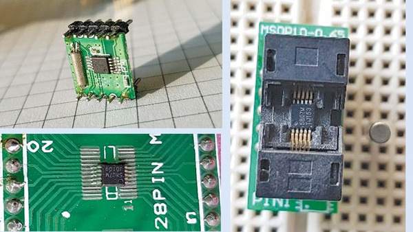
You can use a 2mm header alongside the RDA5807M module, as shown in Fig. 13, or opt for an MSOP to DIP adaptor board or a ZIF socket for quick testing and evaluation.
The FM module is capable of driving earphones or headphones with a 32-ohm load. You can use either 32-ohm headphones, 32-ohm earphones, or 32-ohm 40mm speakers, as shown in Fig. 14.

The volume level provided is more than sufficient for listening through earphones or headphones. For additional audio power requirements, you can connect an external power amplifier.
Once you have made all the necessary connections as per the circuit, insert the programmed ESP-01 into the circuit. Connect the earphones/headphones or the 32-ohm speaker to the audio output and attach the antenna wire to the FM module’s pin 10.
Working prototype with MSOP-10 ZIF socket with 2.54mm pitch along with IR receiver, ESP-01, and OLED with RDS display is shown in Fig. 15.
For testing, apply either a 5V or 3.7V power supply. You can change the volume using the remote control’s VOL+ and VOL- buttons and adjust the FM channel frequency using the << (PREVIOUS) and >> (NEXT) buttons on the remote.
Please refer to the NEC code table and the source code for key assignments.
Currently, the remote supports only four functions, but additional features like MUTE, BASS BOOST, and RSSI functions can be easily added, along with modifications to the display for status indications.
You can also assign PRESET stations to remote keys 1, 2, 3, and so on, and store last-used station, volume information, and other status details in internal or external non-volatile memory. This can help boot the radio with the last-used volume and channel frequency information.
Moreover, if you have FM stereo transmitters, you can transmit and receive your own channel with stereo audio signals.
This opens the possibility of operating FM remote speakers similar to Bluetooth speakers for wireless convenience.
POC Video Tutorial In English:
POC Video Tutorial In Hindi:
EFY Note. Please note that not all FM stations transmit RDS information. The OLED display will indicate the RDS message if available from the station; otherwise, it will remain blank.
The author K.N. Antony, with a B.Sc. degree in physics and a B.Tech degree in electronics, holds several US patents and is author of many international publications, including WIPO. His hobbies include RF and audio amplifier design
[ad_2]
Source link