

[ad_1]

The mini light follower robot proposed here works in ambient light. It employs sensors to detect variations in light intensity, which allows it to navigate and perform tasks in diverse environments.
This mini-robot exploration combines robotics and light-sensing technology, showcasing the potential for autonomous systems to adapt to changing light conditions. The block diagram of the light-follower robot is shown in Fig. 1.
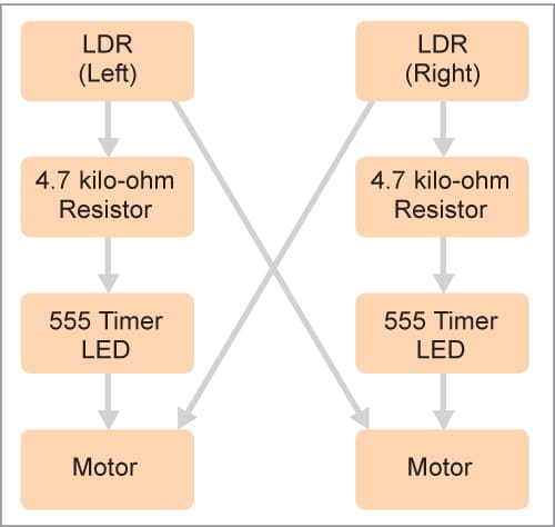
This mini-robot introduces a captivating exploration into the realm of robotics by combining the light-dependent resistor (LDR) and the 555 timer IC. The core concept involves creating a light-activated robot, where the LDR functions as the sensory ‘eyes,’ and the 555 timer serves as the controlling ‘brain.’
As light intensity changes, the resistance values of the LDR detect these variations, prompting the 555 timers to orchestrate the robot’s movements. The result is a robot that dynamically responds to its environment, moving in coordination with the presence or absence of light.
This hands-on endeavor provides a foundational understanding of sensors, timers, and motor control, bridging the gap between theory and practical application.
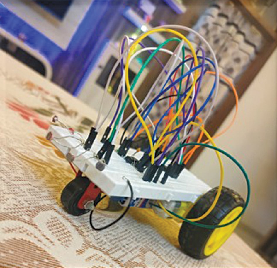
The light follower robot’s prototype on a breadboard is shown in Fig. 2.
Light Follower Robot Circuit and Working
Fig. 2 shows the circuit diagram of the light-following robot. It is built around two 555 timers (IC1, IC2), two DC motors (M1, M2), two light-dependent resistors (LDR1, LDR2), and a few other components. For the power supply, a 9V power adaptor or a 9V battery may be used.
| Parts List | |
| Semiconductors: | |
| IC1, IC2 | -555 timer |
| Resistors (all 1/4-watt, ±5% carbon): | |
| R1-R4 | -4.7-kilo-ohm |
| Capacitors: | |
| C1, C2 | -0.01µF polyester |
| Miscellaneous: | |
| LDR1, LDR2 | -Light-dependent resistor |
| M1, M2 | -12V DC motor |
| -Robot assembly | |
| -Two wheels | |
| -One small moving wheel | |
| -Jumper wires, male-to-male | |
| -Breadboard | |
| -9V DC battery/adaptor | |
The idea behind the light-activated robot is to create a versatile and adaptive robotic system that can respond to changes in lighting conditions. Light sensors enable the robot to perceive its surroundings and make decisions accordingly.
The circuit comprises two divisions: one is LDR, the light-sensing element, and the other is the 555 activator. The LDR1 is paired with resistor R1 to form a potential divider to feed the trigger voltage to the IC 555 (IC1). It gives maximum voltage when no light is incident on it and minimum voltage when light falls on the LDR.

The resistance of the LDR is inversely proportional to the intensity of light falling on it. It implies that if the intensity of incident light is high, the resistance of the LDR will be less, and vice versa.
The activator is built around a 555 IC, which is wired as an astable multivibrator. This principle is used here to make the 555 act as a switch when light is incident on the LDR.
The working of this robot is simple. Timer IC 555 gets activated when its discharge pin 7 receives a voltage greater than 0.8V. Once the IC is activated, the voltage at pins 2 and 6 needs to be between 1/3rd and 2/3rd of the supply voltage for the output to be high.
For example, if the voltage at discharge pin 7 is above 0.8V, and the voltage at pins 2 and 6 is half the supply voltage, the output goes high to turn the motor.
In the circuit, a voltage divider is created using the LDR and a resistor. It is then connected to the 555 timer IC. When it’s dark, the LDR’s resistance increases, and the voltage at the voltage divider drops below 0.8V, causing the 555 timer IC output to go low to turn off the motor.
When there is enough light, the voltage at the discharge pin 7 goes above 0.8V, and the 555 IC output goes high to turn on the motor.
Construction and Testing
Before assembling the circuit based on the circuit diagram shown in Fig. 3, also refer to Fig. 2. This will give an exact idea about the construction of the robot. Assemble the circuit directly on the breadboard and use a cabinet and wheels in such a way that the robot can smoothly move when light falls on the LDRs. LDRs are mounted on the top of the breadboard in such a way that light should fall on them for the proper movement of the robot.
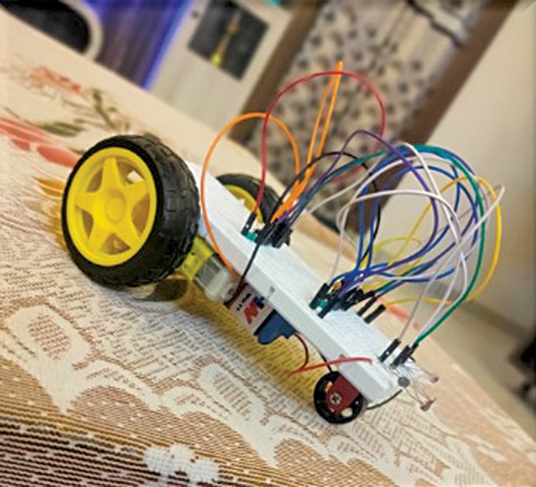
After proper assembly, your light-activated robot is ready to use. When light falls on LDR1 or LDR2, respective motors rotate accordingly, resulting in the robot’s movement. An image of a ready-to-use robot on a breadboard is shown in Fig. 4.
Authors: Manmohan Singh, Vivek Gowda, Ramiksha Shetty, and Sahana P from the Electronics and Communication Department, Sapthagiri College of Engineering, Bengaluru
Source link