[ad_1]

This Arduino-based night security light can protect your home/office from thieves/intruders at night. The light glows when movement is detected in front of the PIR sensor. Simultaneously, a piezo buzzer also sounds.
Features of the Night Security Light System:
- Automatic Activation: The light turns on when it’s dark and motion is detected by the PIR sensor.
- Duration Control: Upon detecting movement, the light remains on for ten seconds. If motion is detected again within this time, the countdown restarts.
- Daylight Sensing: The system remains off during daylight even if motion is detected.
- Incorporation of a Piezo Buzzer: A piezo buzzer sounds simultaneously with the light to alert during intrusions.
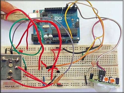
The prototype of the Arduino-based night security light system is shown in Fig. 1.

| Components Required | |
| Semiconductors: | |
| – BC547 NPN transistor | – Arduino board |
| D1 | – 1N4007 rectifier diode |
| Resistors (all 1/4-watt, ±5% carbon): | |
| R1 | – 10-kilo-ohm |
| R2-R3 | – 1-kilo-ohm |
| T1, T2 | – BC547 NPN transistor |
| Miscellaneous: | |
| CON1, CON3, | |
| CON4 | – 2-pin connector |
| CON2 | – 3-pin connector for PIR |
| PZ1 | – Piezo buzzer |
| – PIR motion sensor | |
| – LDR | |
| – Breadboard | |
| – Jumper wires | |
| – 12V, 1C/O relay | |
| – 60W, 20V AC bulb | |
Night Security Light System – Circuit
The circuit diagram of the Arduino-based night security light is shown in Fig. 2. It is built around an Arduino Uno board (board1), PIR sensor connected across CON2, two BC547 npn transistors (T1, T2), a 12V one changeover relay (RL1), small LDR (LDR1), a piezo buzzer (PZ1), a 60W 230V AC bulb connected across CON4, and few other components.

Night Security Light System – Working
The heart of this DIY night security light is the PIR motion sensor. The PIR sensor is made of a special material that is sensitive to infrared (IR) light, which is invisible to human eyes. It can detect intrusions using passive infrared (PIR) technology.
The PIR sensor detects motion by sensing changes in ambient temperature when a human body passes by, effectively controlling the switch when motion is detected.
The PIR module includes two variable resistors, one for time setting and the other for range setting. You can adjust these presets to set the minimum time and maximum range before using them in the mechanism.
During the night, this security light is enabled because of the LDR used in the project. The LDR (light-dependent resistor) measures the light level.
At night, the voltage at A1 (pin10) of the Arduino Uno board will be high due to the high resistance of the LDR, enabling the circuit.
In contrast, during the day, the voltage at A1 will be low due to the low resistance of the LDR, disabling the circuit.
So, this night security system is triggered when a logic high-level signal is detected at its sensor input port (A1 of Arduino Uno board). Only one output (D6 pin21 of Arduino Uno board) is used, which is connected to both transistors T1 and T2.
The operation of the circuit is straightforward. At night, when an intruder comes within the PIR sensor, the logic input at pin A1 goes high.
In this condition, output D6 is also high, which makes both transistors T1 and T2 conductive. Transistor T1 drives the relay, and transistor T2 drives the piezo buzzer.
As a result, relay RL1 is energized, turning on the light by providing 230V AC via its contacts. Simultaneously, the piezo buzzer sounds. Both the buzzer and the light remain enabled for ten seconds to alert security at the gate.
Also Check: Innovative Arduino Projects
Arduino Code
The logical software is written in Arduino IDE version 1.8.5.
Before uploading the given sketch to the Arduino Uno board, ensure that you select the correct board.
After selecting the port, upload the sketch file ‘Nightsecuritylight.ino’ to the board. Fig. 3 shows a screenshot of the source code.

Construction and Testing
To upload the source code, use a USB cable to connect the Arduino board to a laptop/desktop. After uploading the source code, remove the USB cable and connect a 12V DC battery to the board to power the project.
Next, you can assemble the circuit based on the circuit diagram and enclose it in a suitable small box, including the Arduino Uno board.
Position all LDRs at the top of the box so that they receive light during the day. Ensure that the bulb’s light does not fall on the LDR.
Attach the bulb and buzzer to the rear side of the cabinet. You can extend the bulb using twin wires to a suitable location as desired.
Also, install the PIR sensor on one side of the cabinet so that it can capture/detect a person’s movement. Instead of a 12V battery, you can use a 12V power adaptor at the DC terminal of the Arduino Uno board.
Also Check: Midnight Security Light
Step-by-step Video Tutorial
You can watch the video of this DIY Arduino-based Night Security Light System project below-
If you have any doubts or suggestions, please feel free to share in the comments below.
S.C. Dwivedi is an electronics enthusiast and circuit designer at EFY
[ad_2]
Source link

