[ad_1]

The 555 timer has been a popular choice in electronics for a long time due to its versatility and wide range of applications.
It can be used as a timer, oscillator, frequency divider, frequency modulator, triangular signal generator, and more.
You can check the Interesting 555 Timer Projects.
The 555 timer has three main modes: monostable, astable, and bistable.
In this article, we will explore a new mode of operation for the 555 timer that generates a unique pulse when the circuit is powered on.
Unique Mode of Operation for the 555 Timer
The only way to generate another pulse is by turning off the circuit and then powering it on again. While one might think that this can be achieved with the monostable mode by setting pin 2 to low (ground), doing so would result in the output of the 555 timer always being on.
(You can try this yourself)
In this particular monostable mode, pins 5 and 7 are not used. Fig. 1 illustrates the circuit diagram of this specific monostable circuit.
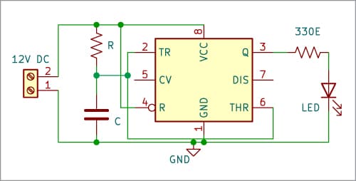
This new configuration of the LM555 timer in monostable mode can be used in various applications, such as alarm systems in cars, turning on a computer in a car, and creating an automatic dispenser for soap or antibacterial gel.
How does this Unique Mode Work?
To explain the operation of this new mode, let’s refer to Fig. 1. When the circuit is powered on, capacitor C initially has no voltage, resulting in both pin 6 and pin 2 of the 555 timer having a voltage of zero.
In the reset comparator, the inverse input of the comparator has a voltage of (2/3)VCC, while the non-inverse input has a voltage of zero. As a result, the internal comparator output is low.
Now, let’s consider the set comparator. At this time, the inverse input is at 0V, and the non-inverse input is at (1/3)VCC. Consequently, the comparator output will be high.
In conclusion, when the capacitor has some voltage, the output of the 555 timer will be high.
While the capacitor is charging, the circuit continues with its output in the high state. The output of the 555 timer goes low only when the voltage in the reset comparator exceeds (2/3)VCC.
When the output of the 555 timer is low, the capacitor cannot discharge through pin 7 since this pin is not used in this configuration. Thus, the 555 timer cannot generate additional pulses.
Therefore, the only way to generate a new pulse is to turn off the circuit and then turn it on again.
Automatic Dispenser Using LM555
Many people have attempted to create automatic dispensers using an Arduino with an infrared module, while others have used just the module itself.
However, using an Arduino Nano for this purpose can be more expensive than using a 555 timer. Some dispensers do not require a microcontroller or an Arduino; they work directly.
If you put your hand near the dispenser and keep it there, the dispenser will dispense soap or gel until you remove your hand, potentially resulting in excess usage.
A commercial automatic dispenser dispenses soap or gel for a specific amount of time. Even if you trigger the sensor multiple times, the dispenser waits until you remove your hand from the sensor before allowing you to dispense again.
Circuit and Working
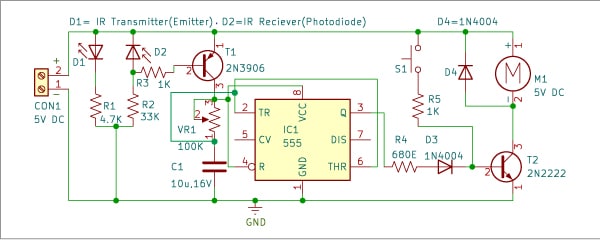
Fig. 2 presents the circuit diagram of the automatic dispenser. It consists of an IR transmitter (emitter), an IR receiver (photodiode), rectifier diodes 1N4004 (D3 and D4), PNP transistor 2N3906 (T1), NPN transistor 2N2222 (T2), an LM555 (IC1), a 5V DC motor, and a few other components.
| Parts List | |
| Semiconductors: | |
| IC1 | -555 timer |
| D1 | -IR transmitter |
| D2 | -IR receiver |
| D3-D4 | -1N4004 diode |
| T1 | –2N3906 PNP transistor |
| T2 | -2N2222 NPN transistor |
| Resistors (all 1/4-watt, ±5% carbon): | |
| R1 | -4.7-kilo-ohm |
| R2 | -33-kilo-ohm |
| R3, R5 | -1-kilo-ohm |
| R4 | -680-ohm |
| Capacitor: | |
| C1 | -10μF, 16V electrolytic |
| Miscellaneous: | |
| CON1 | -2-pin connector |
| S1 | -Pushbutton switch |
| M1 | -5V DC motor |
| VR1 | -100 kilo-ohm potentiomete |
The sensor of the dispenser is a combination of an IR emitter diode and a photodiode placed face to face, so they have a line of sight, the light of the IR emitter diode we cannot with eyes.
When the emitter and diode have a line of sight, the photodiode conducts energy because the light of the emitter triggers the photodiode and when some object or a hand interrupts the line of sight, the photodiode does not conduct.
The PNP transistor 2N3906 conducts only when its base pin is at 0V or ground voltage. If it has 5V at its base, it will not conduct.
Therefore, when we place our hand between the emitter and the photodiode, the base of the PNP transistor goes to 0V. Consequently, the output of the 555 timer at pin 3 generates a pulse, which is then sent to transistor T2 to activate the DC motor that dispenses the soap based on the time set by capacitor C1 and potentiometer VR1.
It’s important to note that this particular monostable mode of the 555 timer sends only one pulse. Even if you don’t move your hand (obstructing the line of sight), the only way the automatic dispenser will dispense again is by removing your hand, which turns off the 555 timer.
When the line of sight is obstructed again, the dispenser will dispense soap once more.
The potentiometer in this circuit is used to adjust the dispensing time of the dispenser. We recommend a range of 0.5 to 1.2 seconds. The precise time depends on the tests you conduct and the viscosity of the soap or gel.
In the circuit diagram (Fig. 2), you will notice a push-to-on switch (S1). This switch is used for dispensing without using a sensor. To build this automatic dispenser, we recommend using a self-priming gear motor.
If possible, reuse a gear motor pump from an old commercial dispenser whose electronic board may have been damaged.
PCB Design
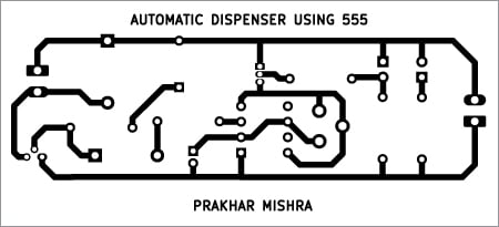
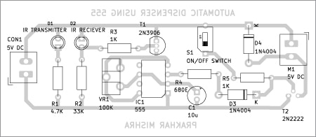
Fig. 3 shows the actual-size, single-side PCB layout for the automatic dispenser using the LM555. The component layout can be seen in Fig. 4. Once you have assembled the circuit on the PCB, enclose it in a suitable box.
Construction and Testing
For fitting the motor with the soap disposal mechanism, refer to Fig. 5. Place the switch in front of the cabinet for manual use.
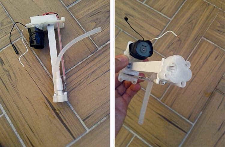
Fig. 6 displays the author’s final prototype, excluding the motor and soap disposal pump, which need to be connected externally using wires.
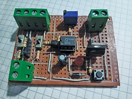
After fixing the motor as shown in Fig. 5 and assembling the components as shown in Fig. 6, interconnect both and install them at a proper location based on your choice.
Other DIY Dispenser Projects
Santiago Echeverry Serna is an electronic engineer from Medellín-Colombia, who likes to ride bicycles and play basketball. He is an electronics enthusiast who likes to make simple circuits without programming
Source link

